
3 Phase 12 Lead Motor Wiring Diagram
A 3 phase motor is a type of AC motor that operates using three separate phases of electrical current. These motors are commonly used in industrial and commercial applications due to their efficiency and ability to produce high torque. Understanding the basics of how a 3 phase motor works is essential for anyone working with these types of motors.
Wiring Diagram For Motor Starter 3 Phase Controller Failure Relay 3
Understanding 3 Phase Motor Wiring: A Comprehensive Guide When it comes to industrial and commercial applications, 3 phase motors are the go-to choice for many professionals. These powerful motors offer high efficiency, reliability, and smooth operation.
220 3 Phase Generator Wiring Diagram
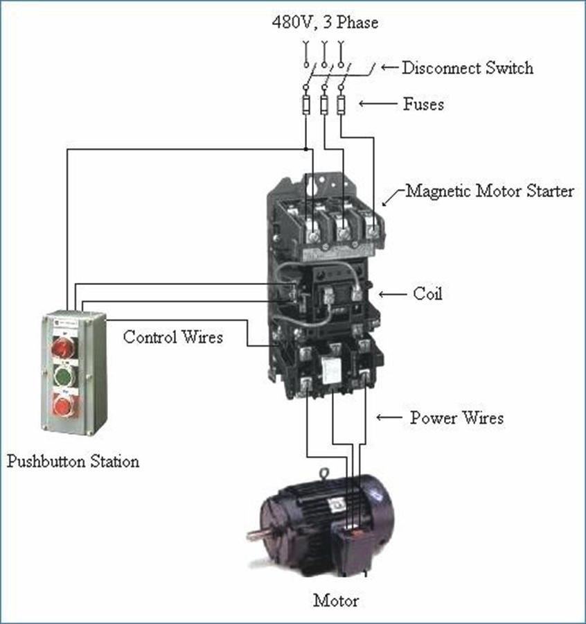
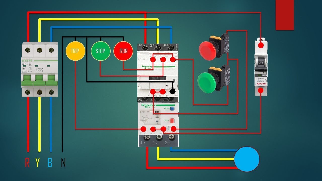
is a typical wiring diagram for a three-phase mag-netic starter. Figure 1. Typical Wiring Diagram Line diagrams show circuits of the operation of the. 3-Phase Motor A1 A2 Remove Wire "C" when it is supplied. Connect Separate Control Lines to the No. 1 Termi nal on the Remote Pilot Device and the
Electric Motor Wiring Diagrams 3 Phase
Figure 1. The internal arrangement of a Wye-wound three-phase motor with nine leads. Those nine leads provide an option for supplying power from either high or low voltage sources. For the low voltage option, the instructions show to connect the following: T4-T5-T6, T1-T7-Line, T2-T8-Line, and finally T3-T9-Line.
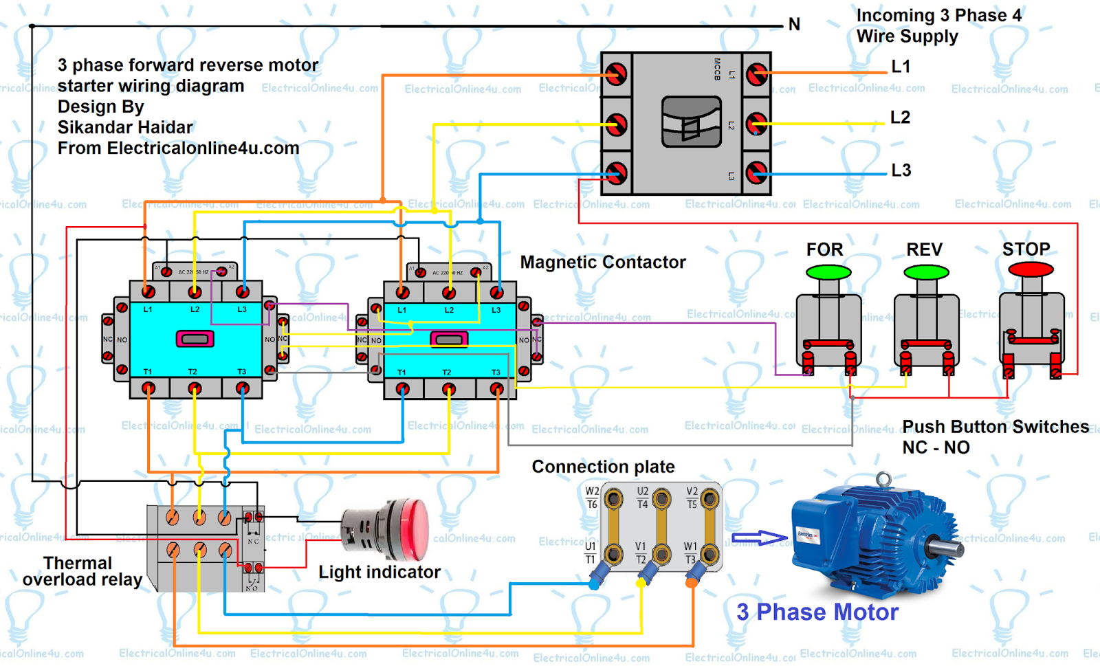
Forward Reverse Motor Control Diagram For 3 Phase Motor
A 3 phase motor is a type of motor that operates with three separate phases of electrical power, and its wiring diagram depicts the connections between these phases and the motor itself. The 3 phase wiring diagram for motors typically includes information such as the voltage and current ratings, the type of motor (e.g., induction motor or synchronous motor), and the connection details.
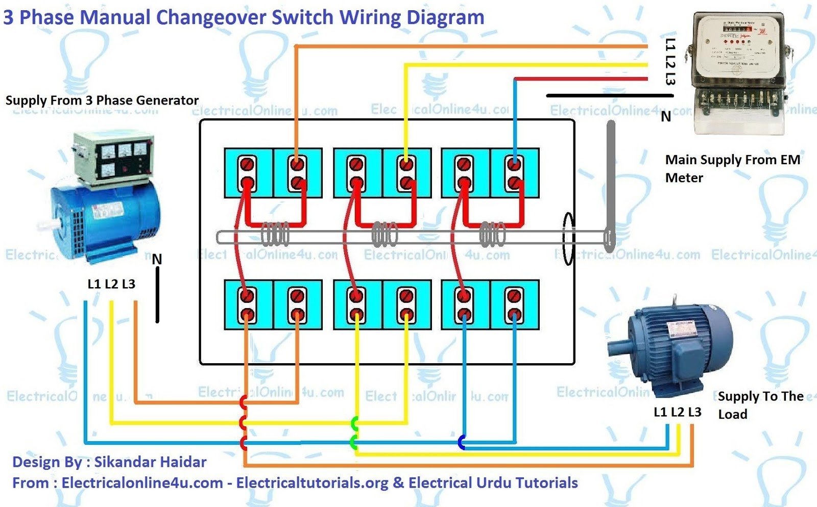
3 Phase Manual Changeover Switch Wiring Diagram For Generator
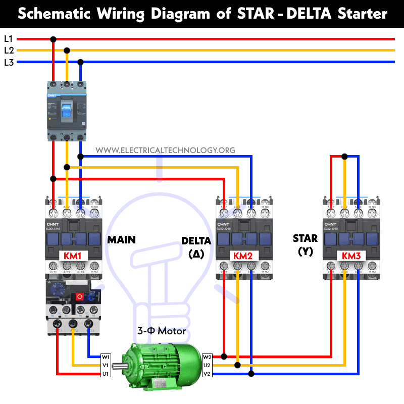
23 1 minute read Three Phase Motor Power & Control Wiring Diagrams Three Phase Motor Connection Schematic, Power and Control Wiring Installation Diagrams. Star-Delta (Y-Δ) 3-phase Motor Starting Method by Automatic star-delta starter with Timer. Three Phase Motor Connection STAR/DELTA Without Timer - Power & Control Diagrams

3 Phase Motor Wiring Relationship Attachment Diagram Wiring23
Three-phase electric motors are a reliable and efficient form of power generation and are often used in industrial applications. However, understanding the circuit diagram can be confusing because of the numerous wires and connections involved.Three-phase electric motors transfer power from one electrical circuit to another through three separate phases, allowing for more efficient motor.
3 Phase Electric Motor Wiring Diagram
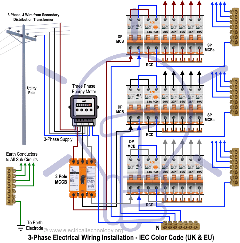
One of the key elements in an electric motor wiring diagram is the power source. It can be a single-phase or a three-phase power supply, depending on the motor's design and application. The diagram also shows how the power source is connected to the motor's windings, which generate the magnetic fields necessary for the motor to operate.
3 phase motor wiring diagrams 230v
Three-phase AC motors can be divided into three general types: squirrel-cage, wound-rotor and synchronous. Only the squirrel-cage rotor motors and the wound-rotor motors are induction motors. The rotor circuit in an induction motor does not have an external power supply.
Wiring Diagram 3 Phase Motor Switch Wiring Diagram
3 Phase Motor Wiring Diagrams | Phoenix Phase Converters Three Phase Electric Motor Wiring Diagrams December 19, 2022 In News 3 comments ALWAYS USE WIRING DIAGRAM SUPPLIED ON MOTOR NAMEPLATE Three Phase - 12 Lead Motor Three Phase - 9 Lead Motor Three Phase - 6 Lead Motor Three Phase - 3 Lead Motor 3 comments

3 phase motor wiring Wire, Diagram, Motor
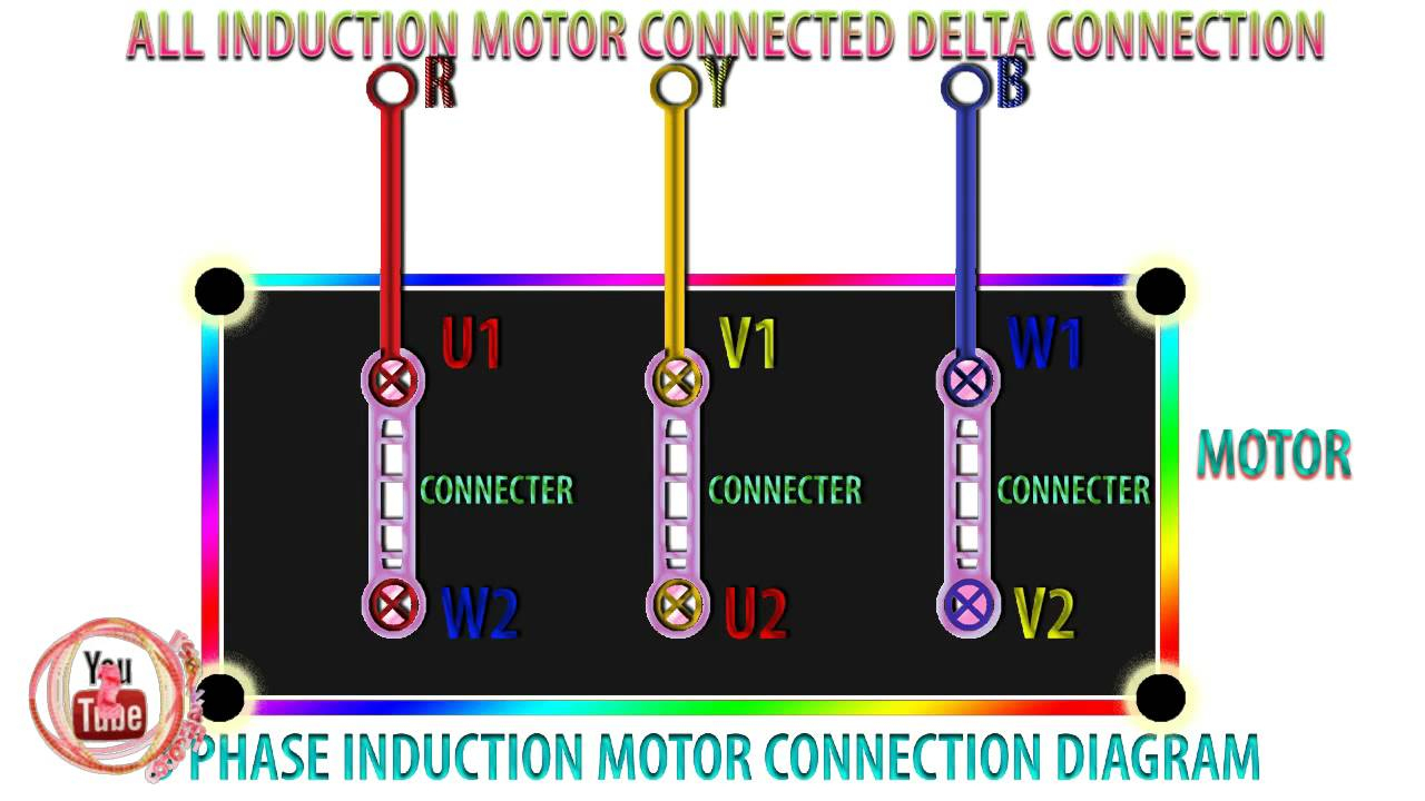
In the diagrams below, the coils are represented with bold lines between terminal numbers on the far right side. The motor will have a junction box on the side with 9 numbered (often colored) wires, and a diagram that looks similar to this on the data plate.
3 Phase Motor Starter Wiring Diagram Database
Three phase motor wiring diagrams are composed of three separate lines, each representing a power phase, and the lines typically form a closed loop. All three lines form a neutral wire, with each being either connected to the other two or completely independent.
Direct Online Starter Animation Diagrams Electrical Online 4u
Step 1: Identify the Wires Identify and sort the 9 or 10 wires. 3 are power wires, and 6 or 7 come from the motor. The wires are color-coded, but some also have numbers written on them. Refer to the wiring diagram on the motor's label. Video | Wayne's Garage Step 2: Choose a Configuration Which configuration should you make?

3 Phase Electric Motor Wiring
Capacitor Motor Single-Phase Wiring Diagrams ALWAYS USE WIRING DIAGRAM SUPPLIED ON MOTOR NAMEPLATE. W2 CJ2 UI VI WI W2 CJ2 UI VI WI A cow VOLTAGE Y HIGH VOLTAGE z T4 Til T12 10 Til T4 T5 ALI L2 T12 TI-BLU T2-WHT T3.ORG T4-YEL T5-BLK T6-GRY T7-PNK T8-RED T9-BRK RED TIO-CURRY TII-GRN T12-VLT z T4 Til T12
3 Phase Motor Wiring Diagram 12 Leads Collection
Step 1 Turn off the power supplying the circuit to be wired to the motor. A three-phase motor must be wired to a three-phase supply. Video of the Day Step 2 Open the motor wiring box and identify the wires within. The nine wires should be labeled 1 through 9.

3 Phase Motor Control Panel Wiring Diagram Home Wiring Diagram
Wiring Diagrams ww introduction. (For 2 Phase, 3 Wire, L2 and T2 are common) Sgl. Phase Lines Sizes 0,l and 1P Single Phase. 2 Phase, 3 Wire (For separate winding motors only) WIRING DIAGRAMS w Bulletin 609U The Bulletins 609U and 609TU are the same as the standard Bulletin 609 Manual Starters except for the addition of Under-.